

How do Coordinate Measuring Machines Work?


Traditional Coordinate Measuring Machines (CMMs) are machines uses to measure an object in 3 dimensions. They come in many different sizes and styles and accuracy ranges. They can be purchased used for a few thousand dollars (be cautious of these) to well over $1,000,000. However at their core, they operate on the same principles.

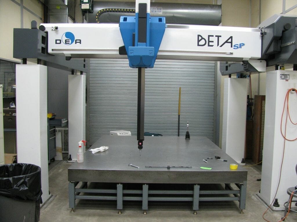
FIGURE 1: A Gantry CMM at 3D Engineering Solutions


FIGURE 2: CMM with major components highlighted. Note that most CMMs have the X and Y axis not as shown but swapped in position from this CMM. This large CMM follows an automotive convention of having the Y axis in the cross car position and the longer X axis in the fore/aft position.
Typical touch-probe CMMs, as seen in figures 1 and 2, have 3 axis of motion (X, Y and Z). These axis are measured using linear scales that precisely determine the location of each axis (In Contrast, Arm based CMMs use rotational encoders offering more flexibility but are generally less accurate). These linear scales are basically strips of material that have many very fine marks on them that correspond to distance (Figure 3). As a machine axis moves an encoder reads these marks and keeps count of how far the machine has actually moved.

FIGURE 3: A portion of a scale. Note the larger vertical marks near the top of the golden colored background and the much smaller marks in the middle section which are read directly read by encoders.

The Z axis (vertical axis) is on the machine quill (Figure 4). At the end of the quill is a Probe Head (Figure 5) that allows rotation of probes that are placed on the Probe Head. These probes have a sphere at the end of them that are typically made of an industrial Ruby, ceramic, steel or similar material. Materials for probe tips are chosen for their wear characteristics and ability to be made very spherical. These spheres can become damaged by wear and then will no longer be as accurate.
As the CMM moves, the sphere will be caused to touch a surface which causes the probe to deflect after a certain distance/force has been reached. There are a variety of different touch probes that can be purchased to vary this distance/force for different applications. This touch causes a signal to be generated to tell the CMM the location of a point. That point has an XYZ location and an IJK vector (determined by compensation as described below). All of this information about the individual points that the CMM takes is captured by the CMM controller(s) – (its computer shown in Figure 6). The controller is connected to a PC that runs software that interprets the controller information. The collection of points taken by the CMM is known as a point cloud. The point cloud for an inspection could have only a few points for small programs to thousands of points for larger ones. With scanning probe heads or optical type scanners, the point cloud can be millions.

FIGURE 4: Image of the quill that has a probe head and probe attached near the bottom. This forms the Z axis of the machine.

FIGURE 5: Image of a probe head (black component), Touch probe (dull silver component) and Probe (think component with Ruby sphere).

FIGURE 6: The CMM controller that acts as the interface between the PC and the CMM.

The CMM knows precisely where the center of the sphere is. Since the sphere surface and not the center of the sphere is making contact with the part being measured, the CMM does inherently not know exactly where to register the point location (Figure 7). It must use compensation to determine this.
Compensation is the process of determining how to adjust the XYZ value of the point taken by the CMM so that it relates to the actual location of the surface. If you are taking many points to capture a circle or cylinder for example, the CMM software is smart enough to know if you are taking the points from inside a cylinder or from the outside of the cylinder (Figure 8). It can then quickly determine where the center of the circle is and then compensate the location of the center of each point to the surface of the probe sphere where it made contact with the part. The same rationale goes for determining compensation for planes. As the CMM takes points for a plane feature, the original points are taken at the center of the probe spheres. The software knows what direction that it took those points from (from the top for example) and then can know what side to ‘compensate’ to determine the precise location of the real plane that was probed.

Figure 7: Probe detail highlighting center point of sphere which is captured by the CMM and the actual part contact point which is arrived at by compensation.

Figure 8: Features being probed by CMM. Since the CMM knows the direction the probe is coming from and the radius of the sphere, it can quickly determine where to place actual points on the surface by using information from other points also taken and knowing that a cylinder or plane is being acquired, as in this case.
The user tells the CMM software what type of probe (length of the shank of the probe, diameter of the sphere of the probe and any other accessories). Before an inspection begins, the user will calibrate the probe against a known artifact (typically a well-polished and calibrated sphere as in Figure 9). This probe calibration process happens by allowing the probe to contact the artifact from all sides with many points. This allows the CMM software to know the character of the sphere (its roundness or if it has any defects), so that this information can be used in the compensation process.


FIGURE 9: Calibration spheres used to calibrate / characterize probes.
Once the probe configuration is qualified (characterized), the inspection can begin. The first thing to do is to tell the CMM where the part you are measuring is in relation to the machine. This is done through an initial alignment. This is a useful step if you have a CAD model of the part as it allows the software to know where the part is in space related to the CAD model. You can also take measurements without a CAD model. However, it is just not as convenient.
Beyond the traditional CMMs, there are other equipment and CMM attachments that capture very large point clouds. Some CMMs have probe heads that ‘scan’ (meaning they drag the probe along a surface and continually take points). Others have laser scanners, structured light scanners and optical scanners that attach to the probe head and capture massive amounts of points at once. A large traditional CMM program might have 10,000 points in its point clouds. These other scanning devices can easily capture millions of points!

While they may have more information, they are always a bit less accurate than single point probing CMMs. These other scanners are, in my opinion, the best of both worlds by combining non-contact measurement, an incredible amount of points collected and the superior positioning accuracy of traditional CMMs.
Each year the CMM hardware and software continue to improve and offer new capabilities and improved accuracies. But at their core, they all operate on the same principles. For more information on CMM hardware and software see https://www.3d-engineering.net/dimensional-inspection/.